We consider the flow regime is iso-volume or stationary
(that the fluid is incompressible liquid or of constant density, gas)
-
The flow of a fluid may be, volume flow or mass flow
Mass flow =volume flow x density
-
The volume flow can be calculated with the average velocity of the fluid and the pipe section:
Volume flow (m3/sec)= section(m²) x average speed (m / sec)
- The volume flow can be calculated with with the volume of fluid and the flow time:
Volume flow (m3/sec)=volume of fluid passed (m3) / flow time (seconds)
- relations that bind the volume flow and the fluid velocity, to the different sections are set out in the continuity equation
- The head loss are directly related to the fluid velocity, and therefore to the dimensions of the conduits sections.
For compressible fluids (gas or air):
The gas being compressible, it is possible to change a volume of the same amount of gasby compressing or changing its temperature. It becomes very difficult to speak of a quantity of gas volume without giving the pressure and temperature of the gas when the volume was measured. It would be difficult to give a temperature and pressure whenever we speak of a volume of gas. Then the temperature and pressure at the time of measurement of the volume, are normalized at called normal conditions. This is called normal m3.
Attention, there are two standards, and thus potential errors in conversions:
same pressure of 1013 millibars (average atmospheric pressure) for 2 standards:
DIN 1343 : temperature 273.15K (0°C)
ISO 2533 : temperature 288.15K (15°C)
For calculations of head loss, the size of volumes of gas (compressed or not) moved into the ducts must be given in cubic meters (m3).
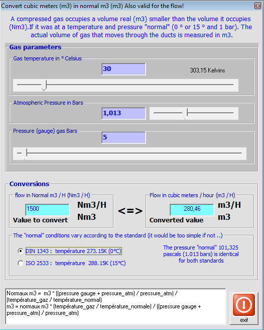
For conversions or Nm3 Nm3 m3 / h m3 / h:
P1V1/T1 = P2V2/T2
p1 and T1 being normal temperatures and pressures v1 is the normal volume (relaxed)
p2 and T2 being the temperature and pressure gas V2 is the volume of the compressed gas
with:
P = Absolute pressure (gauge pressure + atmospheric pressure)
V = volume
T = temperature Kelvin
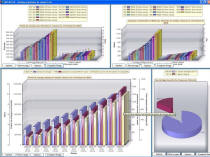
A graphical analysis tool based on the flow can test your network in a flow range selected, and create graphs showing variations of pressure, loss, and energy consumption, depending on the flow. This tool is very effective for the choice of material, in terms of annual operating costs.

- 1 select fluid
- 2 enter volume flow
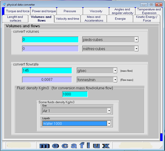
integrated converter mecaflux
The conversion interface normal volume (nm3) and real (m3) converts the normal flow (Nm3 / h) to real (m3 / h)

